Data file handling
Overview
The Pundit Vision modules work with a common file format for measurement data and reconstructed data. The original format was created with a Fortran background, where binary data were organized as records with fixed record length. This was always the fastest way to read and write data to disks and over the net.
There are two ways to handle ghk files:
All data of a measurement or a reconstruction are in one big file. The description of the file content is defined in a small binary header which is part of the file.
The data are in a binary file with fixed length for each A-Scan. To read this file, there must be a header with the information which is necessary to handle that file.
For maximum compatibility the header is in both cases the same with the difference of “one” flag: “As reference”. If this flag is zero, then the data must follow the header in the file. The length of the header is minimal 1024 bytes but the space between the header and the data in the file is filled with zeros until a full record defined by the length of one A-scan (in byte) is reached. 1 We call this header rf_header or ghk_header.
The description of the binary data by the header is very flexible, so that we can read most types of binary files with fixed A-scan length.
- Remark:
The data written by Pundit Vision modules are always in format b) and the data type is always float (4 bytes) or complex (8 bytes). With the browser module exists the possibility to export data without a header.
- Byte ordering:
The header of a ghk file must be written in the same byte format (little endian / big endian) like the data. The files are always written in the format of the actual machine. The format of a ghk file is detected during reading and converted automatically.
In the beginning, the measurements were defined on rectangular grids and expected as impulse-echo measurement. Later, the measurement type was enhanced to linear arrays and arbitrary arrays.
We use always a rectangular coordinate system (x,y,z) on the top of the test object (Local Coordinates).
Usually the x-coordinate is the scanning direction or the direction of the long axis of the linear array.
The y-axis is orthogonal to x: the distance between scan lines is delta_y
The z-axis is perpendicular to the surface. The negative z-direction points into the material block.
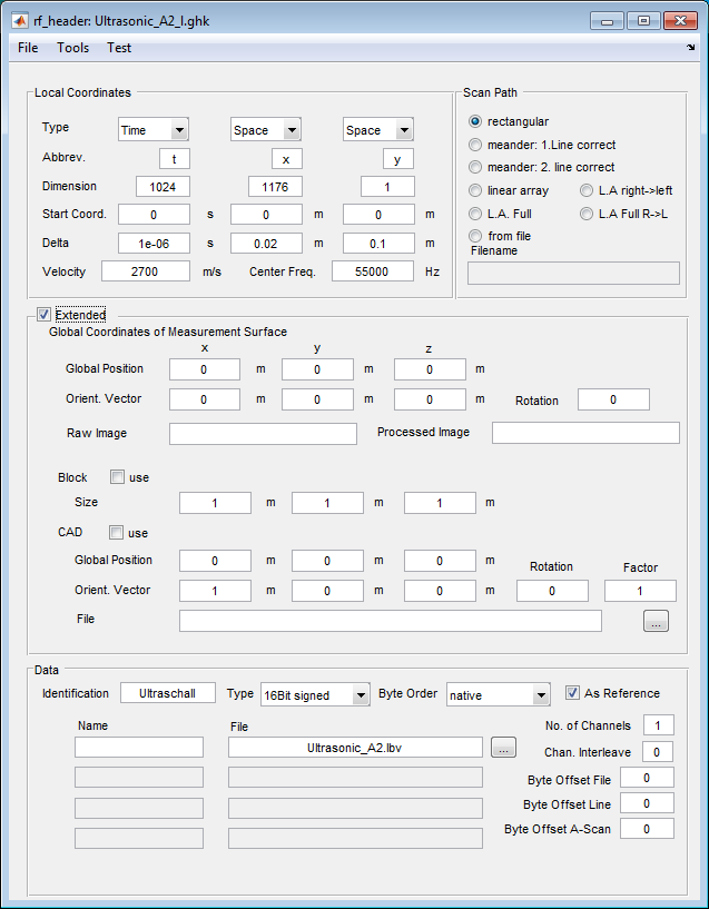
For definition or changes of the header of ghk-files the rf_header module is provided (Pundit Vision -> modules -> edit header). This module may also be called from within other modules.
The types of measurements
regular (rectangle) scan path: the definition is given in the header by the x and y (space) columns. The type of scanning can specified in the “Scan Path” section.
“rectangular”: the data are arrange in parallel lines, the scanning is for each line in the same direction
“meander: 1. line correct”: the lines with odd numbers are oriented as described by the x-column. The even numbered lines are reverse oriented.
“meander: 2. line correct”: the even numbered lines are described by the x-column. The odd lines are reversed.
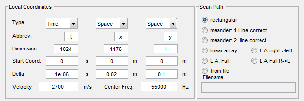
Typical coordinate section for impulse echo (t,x,y)-data
Linear Array
The header of ghk-files are only useable for one array position or for columns of array positions with a distance in y-direction. In the “Scan Path” section linear array indications must be selected. The distance of the elements is defined by delta_x (0.03m). The number of A-Scans for one measurement is defined by dimension_x (66). The real extension is calculated by the type of the linear array:
“Linear Array”: First transmitter on the left side. The receivers are always on the right side of the transmitting transducer.
“L.A. right->left”: Reverse: first transmitter is on the right side.
“L.A. Full: full array:” for each transmitter, all other receivers catch the data; first transmitter on the left side.
“L.A. Full R->L: Reverse:” everything is arranged from right to left.
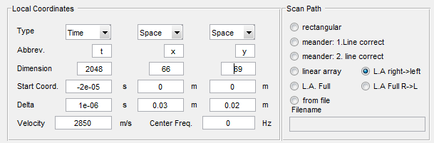
Typical coordinate section for linear array measurement (t,x,y)-data
Arbitrary measurement positions:
Sender and receiver at the same position (impulse-echo or common offset)
Sender and receiver at different positions
With InterSAFT we can handle only case 1. The interpretation of data and the calculation time is not suited to be handled interactively.
The position information is usually not stored in the header (there are some exceptions). The information is stored in so called scan path files.
More complex types of measurements
As mentioned the ghk-header can only handle (t,x,y) data, where x and y are equidistant. For more complex arrangement there is a method to combine ghk-files with a combination file. We call this type of file: “Series Definition File”.
With “Series Definition Files” it is possible to collect ghk-files of type 1, or ghk-files of type 2. This means we can collect binary files with header or binary files without a header like “.lbv” files or “.raw” files.
The “Series Definition File” contains headers of all files or a common header for all files and additional information about the position arranged in columns and rows. Even the possibility to provide a separate scan path file for each measurement is implemented.
“Series Definition Files” can be used in InterSAFT and in SurfaceWaves instead of ordinary ghk- or lbv-files. See InterSAFT for more details.
Data section of rf_header
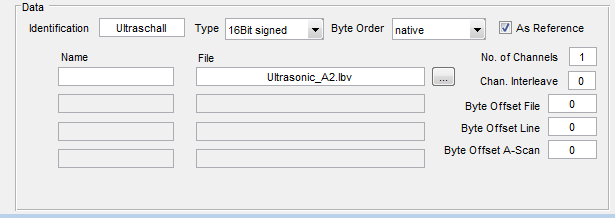
Typical data section for impulse echo (t,x,y)-data
Assume we have some external binary data. These data have a number format (signed integer 8 bit, signed interger 16 bit, signed integer 32 bit, 4 byte float, 8 byte complex or one byte unsigned. We can select different parameters and identification strings to assign up to 4 channels (preserved for different polarisations or other data for the same position information). Put the cursor over the fields and you will see small information strings (tool tips) about the respective field.
Extended section of rf_header
This section is used to give additional information about the global position, the extension of a specimen (block) and CAD file. This section is used for 3D visualisation. It has no influence on the reconstruction algorithm. The section can be switched off by the flag “Extended”.
For Pundit data check | |
There are some predefined ghk header files for different binary files available. If you open “lbv” or “raw” files in InterSAFT you will see a list of header files which are located in the user_setting directory and start with a name like “default_lbv_header…”.
- 1
Because of a very early decision the calculation of the first data position is given by a function:
function ds=datasection(nt,dt)
ds=nt*sizeof_GHK(dt); % length of one A-Scan in bytes
while ds < 1024
  ds = ds + ds;
end