Non-Destructive Subsurface Mapping and Condition Assessment of a large Highway Bridge
This application note details a comprehensive non-destructive evaluation (NDE) workflow used to assess the structural integrity, reinforcement layout, and waterproofing condition of a major highway bridge.


Newsletter
Get the best NDT and InspectionTech content delivered straight to your inbox
Comprehensive Bridge Deck and Waterproofing assessment with multichannel GPR
The Challenge
To ensure long-term asset management and plan targeted maintenance, the asset owner required a detailed assessment of a key highway bridge's internal structure and waterproofing condition. Specifically, the inspection faced several critical hurdles:
- Undocumented Internal Geometry: Up-to-date, highly detailed drawings of the upper reinforcement layer and the exact layout of the transverse post-tensioning (PT) system were unavailable.
- Waterproofing Degradation Suspected: Moisture ingress was suspected, but its extent, location, and effect on the waterproofing bond beneath the ~100mm asphalt layer were unknown.
- Limitations of Automated Diagnostics: Standard automated GPR deterioration mapping algorithms could not be used due to two compounding factors:
-
- The highly irregular, "patchy" layout of the first-layer reinforcement mat.
- High subsurface water concentration resulting from three days of continuous rainfall prior to the night scan.
- Minimizing Traffic Disruption: The diagnostic work had to be completed rapidly with minimal physical coring or destructive testing.
The Solution
An advanced Proceq Ground Penetrating Radar (GPR) was deployed, combining high-resolution data acquisition with targeted physical validation.
1. High-Resolution GPR Scanning
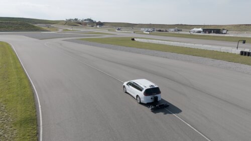
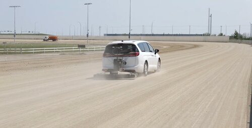
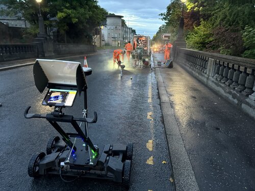
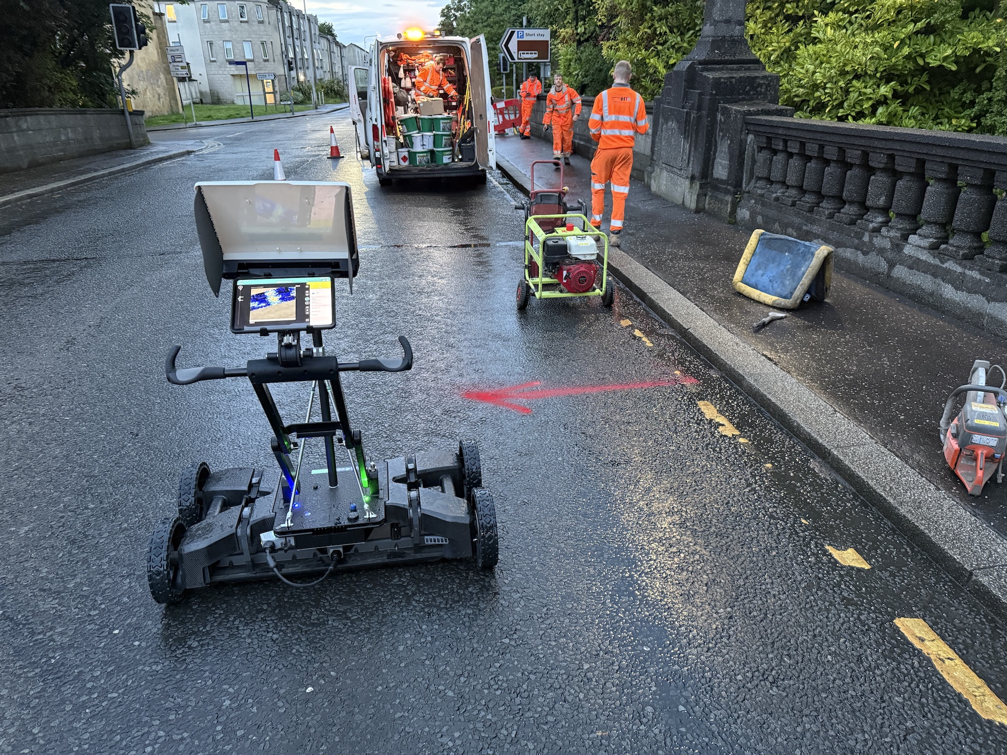
The GPR survey was executed at night using the GM8000 and GS9000 multichannel systems to capture high-density subsurface profiles across the carriageway.
2. Multi-Layer Signal Analysis
Because automated mapping algorithms were unfeasible under the highly saturated conditions, engineers manually analyzed the raw radar dielectric properties and signal amplitudes:
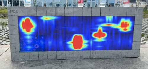
- Waterproofing Boundary Mapping: Evaluated the signal strength at the asphalt-concrete boundary. Low-amplitude reflections (orange/green zones, Fig.3) indicated dry, intact waterproofing, while high-amplitude/high-dielectric reflections (red zones, Fig. 3) pointed to water accumulation and potential debonding.
- Rebar and PT Mapping: Tracked the hyperbola reflections of the longitudinal and transverse steel to map the depth, spacing, and structural relationship between the rebar panels and underlying post-tensioning ducts.
3. Calibration via Targeted Trial Pits
Rather than widespread destructive testing, only three localized trial pits were excavated to calibrate and confirm the GPR signal interpretations:
- Trial Pit 1 was placed in a high-amplitude zone to verify suspected waterproofing failure.
- Trial Pit 3 was placed in a low-amplitude (orange) zone to confirm healthy, intact waterproofing and dry concrete.
Results
The GPR investigation provided a clear, actionable map of the bridge’s internal condition, allowing the client to transition from generalized maintenance to highly targeted localized repairs.
Structural Layout & Reinforcement Mapping
The GPR survey successfully mapped the complex layout of the bridge's upper reinforcement layers:
- First Layer (Depth: 150mm–200mm): Laid out in rectangular panels at 4m centers. Longitudinal bars sit uppermost, directly resting on transverse post-tensioning strands beneath. This suggests the rebar panel likely sat directly on the PT tendon ducts during the original concrete pour.
- Second Layer (Depth: ~300mm): A secondary reinforcement mat was successfully mapped.
- Structural Anomalies: Identified localized areas where the first-layer steel mat sits significantly deeper (300mm–350mm) over the transverse tendons.
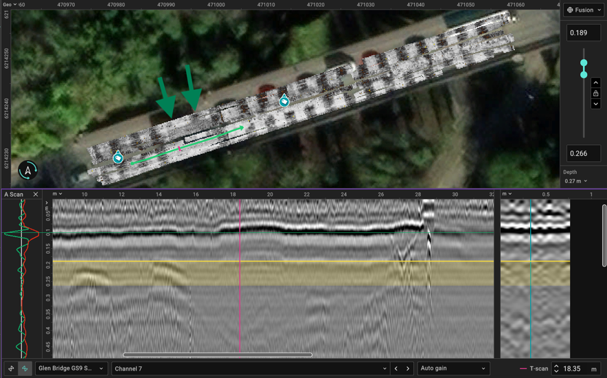
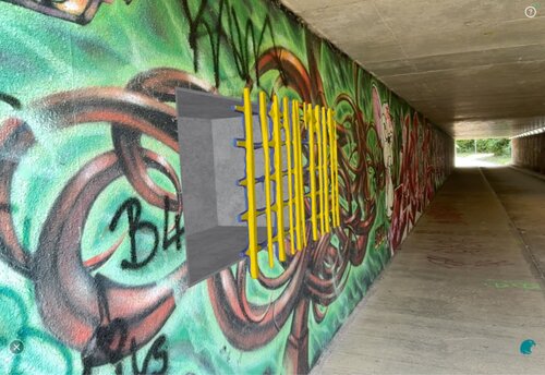
Fig.1 Overview of 1st layer reinforcement
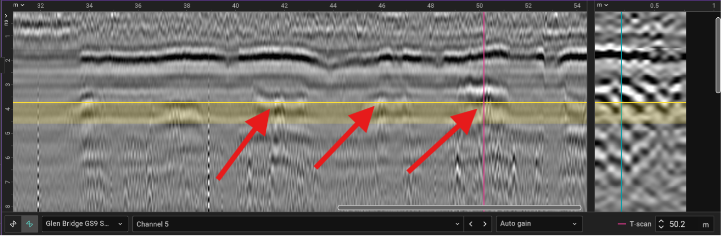
Fig.2 possible PT strands
Waterproofing & Moisture Mapping
By analyzing dielectric contrast at the asphalt-waterproofing interface, engineers isolated areas of moisture pooling:
- Southwest Abutment Joint: A major zone of water accumulation was identified. Due to the slope of the bridge, runoff is stopped hard at the expansion joint, leading to prolonged water saturation. Trial Pit 1 confirmed that this saturation has resulted in a poorly bonded waterproofing membrane.
- Utility Trench Saturation: High-amplitude dielectric responses highlighted a saturated zone running across the carriageway halfway along the span, coinciding with a transverse utility/comms cabling trench.
- Healthy Zones: The westbound carriageway and eastern sections exhibited low-amplitude reflections. Trial Pit 3 calibrated these areas as having fully intact waterproofing and dry underlying concrete.
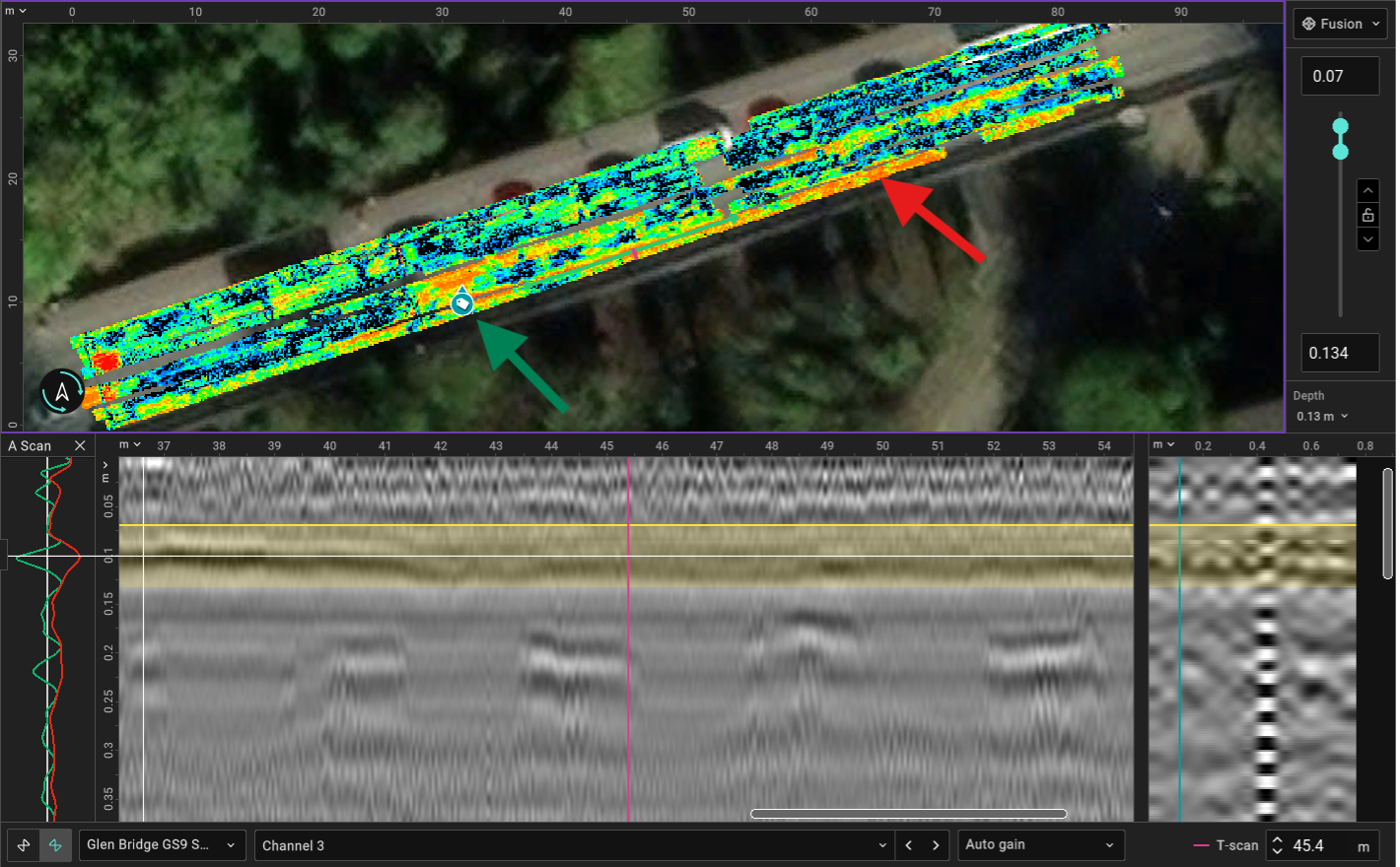
Fig.3 Low amplitude response shown in orange, high amplitude higher dielectric response in red
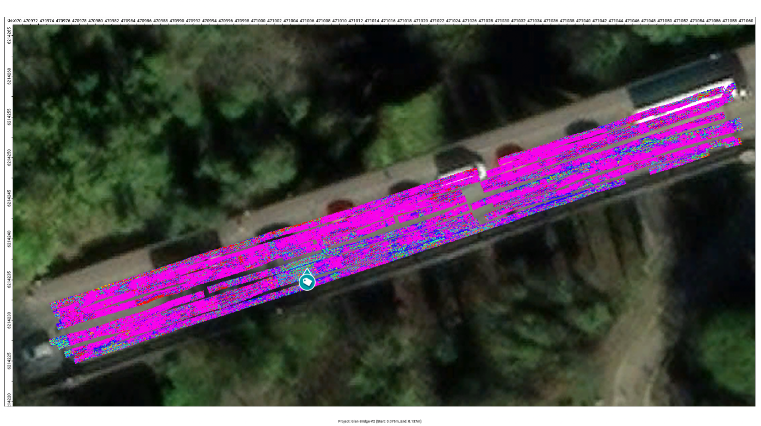
Fig.4 Waterproofing layer
Steel Condition Assessment
Despite the inability to run automated deterioration models, manual signal attenuation analysis successfully flagged localized areas of concern:
• GPR profiles showed a sudden fade/disappearance of the rebar mat corner. This indicates either localized concrete saturation shielding the radar signal or early-stage steel deterioration.
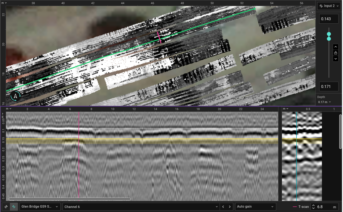
Fig.5 steel detail in centre of bridge
Conclusion & Actionable Recommendations
Overall, the concrete and internal steel reinforcement of the bridge deck were found to be in good structural condition. Rather than recommending a costly, full-deck resurfacing and waterproofing replacement, the GPR data enabled efficient maintenance recommendations:
- Targeted Waterproofing Repair: Execute localized waterproofing replacement on the southwest end of the bridge, focusing on the high-saturation zone up to the easternmost boundary.
- Drainage Remediation: Address the drainage path hard-stop at the southwestern abutment joint to prevent future pooling and premature bond failure.
- Local Concrete/Steel Investigation: Perform a localized, non-destructive follow-up or localized breakout to evaluate the suspected reinforcement degradation.
See more application notes and case studys on our Tech Hub.